HOW TO FACTS AND INFO


TRANSFORMERS

Transformers And How They're Related to Electricity and Electrical


Author: Edis Osmanbasic - 2017

Basic Transformer Theory Background

In the beginning there was no current, either AC or Dc. It took a contest between Edison and Tesla to determine who would be granted the priviledge of powering our country and the method.

The war of the currents was a series of events surrounding the introduction of direct current electricity (DC) Thomas Edison invention –based Edison Electric Light Company and the alternating current (AC) Nikola Tesla invention –based Westinghouse Electric Company. It included commercial competition, a debate over electrical safety, and a nasty media propaganda campaign led by Edison.

Thomas Edison was an American inventor and businessman, who has been described as America’s greatest inventor, and most people would argue that Nikola Tesla was the greatest inventor that the world has ever known.

We were taught that Edison had invented the light bulb, but the truth is that he had purchased the patent from Henry Woodward and Matthew Evans in 1880 and then he hired a team to help him perfect the patent that he made a fortune on. He did however invent the electric chair and apparently had a fetish for electrocuting living animals and people.

It all started in 1882 when Thomas Edison invented the DC or direct current electrical power system. Eventually he hired a young Serbian genius man named Nikola Tesla to help him improve his electrical device. While working for Edison, Tesla discovered how to make his own electrical power system and began building an alternating current system that used a transformer to step up voltage for long-distance transmission and then stepped it back down for indoor lighting, a more efficient and less expensive system that directly competed to the Edison DC electricity system.

In brief: AC electricity can travel much further distances than direct current DC. Without AC electricity we would need massive nuclear power-plants in every city throughout the world.

In 1888 George Westinghouse bought the patent for Tesla’s AC generator. As many other electric companies joined in and the use of AC spread rapidly, Edison’s company made claims that alternating current was hazardous and inferior to the patented direct current system. Tesla’s AC generators were spreading across the country faster than the DC electricity alternative. Edison began publicly questioning the safety of the Tesla-created system, stating, “Just as certain as death, Westinghouse will kill a customer within six months after he puts in a system of any size."

In 1893, Tesla’s AC transmission system had been proven superior over the existing DC transmission system. Westinghouse won the bid to supply electrical power for the World’s Columbian Exposition. Nikola Tesla had officially won the war of the currents.

There is a lot more on tesla, including his rift with J.P. Morgan. You can look it up and read all the what if's."

BACK TO THE PRESENT

One of the main reasons that we use alternating AC voltages and currents in our homes and workplace’s is that AC supplies can be easily generated at a convenient voltage, transformed (hence the name transformer) into much higher voltages and then distributed around the country using a national grid of pylons and cables over very long distances.

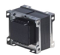
The Voltage Transformer can be thought of as an electrical component rather than an electronic component. A transformer basically is very simple static (or stationary) electro-magnetic passive electrical device that works on the principle of Faraday’s law of induction by converting electrical energy from one value to another. [See picture below]

Single Phase Theory

` Simple Voltage Transformer [Fig. 1
Basic Voltage Transformer [Fig. 1]
` Single Phase Voltage Transformer [Fig. 2]
Single Phase Voltage Transformer [Fig. 2]
` Turns Ratio Formula [Fig. 3]
Turns Ratio Formula [Fig. 3]

Transformers are capable of either increasing or decreasing the voltage and current levels of their supply, without modifying its frequency, or the amount of electrical power being transferred from one winding to another via the magnetic circuit.

A single phase voltage transformer basically consists of two electrical coils of wire, one called the “Primary Winding” and another called the “Secondary Winding”. For this tutorial we will define the “primary” side of the transformer as the side that usually takes power, and the “secondary” as the side that usually delivers power. In a single-phase voltage transformer the primary is usually the side with the higher voltage.

The two coil windings are electrically isolated from each other but are magnetically linked through the common core allowing electrical power to be transferred from one coil to the other. When an electric current passed through the primary winding, a magnetic field is developed which induces a voltage into the secondary winding as shown. [See Fig. 2].

In other words, for a transformer there is no direct electrical connection between the two coil windings, thereby giving it the name also of an Isolation Transformer. Generally, the primary winding of a transformer is connected to the input voltage supply and converts or transforms the electrical power into a magnetic field. While the job of the secondary winding is to convert this alternating magnetic field into electrical power producing the required output voltage as shown.

Notice that the two coil windings are not electrically connected but are only linked magnetically. A single-phase transformer can operate to either increase or decrease the voltage applied to the primary winding. When a transformer is used to “increase” the voltage on its secondary winding with respect to the primary, it is called a Step-up transformer. When it is used to “decrease” the voltage on the secondary winding with respect to the primary it is called a Step-down transformer.

However, a third condition exists in which a transformer produces the same voltage on its secondary as is applied to its primary winding. In other words, its output is identical with respect to voltage, current and power transferred. This type of transformer is called an “Impedance Transformer” and is mainly used for impedance matching or the isolation of adjoining electrical circuits.

Basically, to change the voltage in either the primary or secondary you change the number of coils, or number of times the copper is wrapped around the iron core. This is called a ratio. If you have 3 volts on the primary and the ratio is 3:1 or 3 to 1 the voltage on the secondary would be 1 volt.

Transformers are all about “ratios”. The ratio of the primary to the secondary, the ratio of the input to the output, and the turns ratio of any given transformer will be the same as its voltage ratio. In other words for a transformer: “turns ratio = voltage ratio”. The actual number of turns of wire on any winding is generally not important, just the turns ratio and this relationship is given. [See Fig, 3]

Another one of the transformer basics parameters is its power rating. The power rating of a transformer is obtained by simply multiplying the current by the voltage to obtain a rating in Volt-amperes, ( VA ). Small single phase transformers may be rated in volt-amperes only, but much larger power transformers are rated in units of Kilo volt-amperes, ( kVA ) where 1 kilo volt-ampere is equal to 1,000 volt-amperes, and units of Mega volt-amperes, ( MVA ) where 1 mega volt-ampere is equal to 1 million volt-amperes.

Power in the primary equals the power in the secondary.

It would be nice if transformers were 100% efficient, but they're not. Most transformers average 94% to 96% at full load, which is still pretty good.

Transformers come in all sizes and ratings. Consider the ones outside your home. The voltage being sent down the electric lines or coming in from generating plants are not the typical 120Vac or 220Vac you'd find in your home. Those voltages are average 200Kv up 750Kv. That is enough to kill you many times over.

Three Phase Theory

` 3 Phase Voltage and Currents [Fig. 4]
3 Phase Voltage and Currents [Fig. 4]
` 3 Phase Transformer Example [Fig. 5]
3 Phase Voltage Transformer Example [Fig. 5]
` 3 Phase Delta - Wye [Fig. 6]
3 Phase Delta Wye Configuration [Fig. 6]
` 3 Phase Delta - Delta Connection [Fig. 7]
3 Phase Delta Delta Connection [Fig. 7]
` 3 Phase Star - Star Connection [Fig. 8]
3 Phase Star Star Connection [Fig. 8]
` 3 Phase Star - Delta-Wye Schematic [Fig. 8A]
3 Phase Delta-Wye Schematic Connection [Fig. 6-8A]
` 3 Phase Distribution Schematic [Fig. 8B]
3 Phase Distribution Schematic Connection [Fig. 8B]

So far we have looked at the construction and operation of the single-phase, two winding voltage transformer which can be used increase or decrease its secondary voltage with respect to the primary supply voltage. But voltage transformers can also be constructed for connection to not only one single phase, but for two-phases, three-phases, six-phases and even elaborate combinations up to 24-phases for some DC rectification transformers.

If we take three single-phase transformers and connect their primary windings to each other and their secondary windings to each other in a fixed configuration, we can use the transformers on a three-phase supply.

Three-phase, also written as 3-phase or 3φ supplies are used for electrical power generation, transmission, and distribution, as well as for all industrial uses. Three-phase supplies have many electrical advantages over single-phase power and when considering three-phase transformers we have to deal with three alternating voltages and currents differing in phase-time by 120 degrees as shown to the left: [Fig. 4]

Where: V[L] is the line-to-line voltage, and V[P] is the phase-to-neutral voltage.

A three phase transformer or 3φ transformer can be constructed either by connecting together three single-phase transformers, thereby forming a so-called three phase transformer bank, or by using one pre-assembled and balanced three phase transformer which consists of three pairs of single phase windings mounted onto one single laminated core.

The advantages of building a single three phase transformer is that for the same kVA rating it will be smaller, cheaper and lighter than three individual single phase transformers connected together because the copper and iron core are used more effectively. The methods of connecting the primary and secondary windings are the same, whether using just one Three Phase Transformer or three separate Single Phase Transformers. Consider the circuit to the left: [Fig. 5]

The primary and secondary windings of a transformer can be connected in different configuration as shown to meet practically any requirement. In the case of three phase transformer windings, three forms of connection are possible: “star” (wye), “delta” (mesh) and “interconnected-star” (zig-zag).

The combinations of the three windings may be with the primary delta-connected and the secondary star-connected, or star-delta, star-star or delta-delta, depending on the transformers use. When transformers are used to provide three or more phases they are generally referred to as a Polyphase Transformer.

Three Phase Transformer Star and Delta Configurations

But what do we mean by “star” (also known as Wye) and “delta” (also known as Mesh) when dealing with three-phase transformer connections. A three phase transformer has three sets of primary and secondary windings. Depending upon how these sets of windings are interconnected, determines whether the connection is a star or delta configuration.

The three available voltages, which themselves are each displaced from the other by 120 electrical degrees, not only decided on the type of the electrical connections used on both the primary and secondary sides, but determine the flow of the transformers currents.

With three single-phase transformers connected together, the magnetic flux’s in the three transformers differ in phase by 120 time-degrees. With a single the three-phase transformer there are three magnetic flux’s in the core differing in time-phase by 120 degrees.

The standard method for marking three phase transformer windings is to label the three primary windings with capital (upper case) letters A, B and C, used to represent the three individual phases of RED, YELLOW and BLUE. The secondary windings are labeled with small (lower case) letters a, b and c. Each winding has two ends normally labeled 1 and 2 so that, for example, the second winding of the primary has ends which will be labeled B1 and B2, while the third winding of the secondary will be labeled c1 and c2 as shown. [Fig. 6]

Symbols are generally used on a three phase transformer to indicate the type or types of connections used with upper case Y for star connected, D for delta connected and Z for interconnected star primary windings, with lower case y, d and z for their respective secondaries. Then, Star-Star would be labeled Y[y], Delta-Delta would be labeled D[d] and interconnected star to interconnected star would be Z[z] for the same types of connected transformers.

Transformers for high voltage operation with the star connections has the advantage of reducing the voltage on an individual transformer, reducing the number of turns required and an increase in the size of the conductors, making the coil windings easier and cheaper to insulate than delta transformers.

The delta-delta connection nevertheless has one big advantage over the star-delta configuration, in that if one transformer of a group of three should become faulty or disabled, the two remaining ones will continue to deliver three-phase power with a capacity equal to approximately two thirds of the original output from the transformer unit. [Fig. 7]

One disadvantage of delta connected three phase transformers is that each transformer must be wound for the full-line voltage, (in our example above 100V) and for 57.7 per cent, line current. The greater number of turns in the winding, together with the insulation between turns, necessitate a larger and more expensive coil than the star connection. Another disadvantage with delta connected three phase transformers is that there is no “neutral” or common connection.

In the star-star arrangement ( Y[y] ), (wye-wye), each transformer has one terminal connected to a common junction, or neutral point with the three remaining ends of the primary windings connected to the three-phase mains supply. The number of turns in a transformer winding for star connection is 57.7 per cent, of that required for delta connection.

The star connection requires the use of three transformers, and if any one transformer becomes fault or disabled, the whole group might become disabled. Nevertheless, the star connected three phase transformer is especially convenient and economical in electrical power distributing systems, in that a fourth wire may be connected as a neutral point, ( n ) of the three star connected secondaries as shown. [Fig. 8]

Other possible connections for three phase transformers are star-delta Yd, where the primary winding is star-connected and the secondary is delta-connected or delta-star Dy with a delta-connected primary and a star-connected secondary.

Delta-star connected transformers are widely used in low power distribution with the primary windings providing a three-wire balanced load to the utility company while the secondary windings provide the required 4th-wire neutral or earth connection.

In case of a Y[N] three-phase system, two voltages are available for consumers: line and phase voltage. The voltage that is supplied from the line voltage (U12, U23, U13) by connecting between any two phases, as shown [Fig. 8B]. Otherwise, if the consumer is supplied from the phase voltage (U1, U2, U3), connections between any phase and neutral connection. The line voltage is always higher than phase voltage value. [Fig. 8B]

Most commercial markings for line voltage or inputs are X0 for neutral, X1-X3 for phases. For outputs It's generally H0 (H=High) for neutral and H1-H3 for phases.

` 3 Phase Square D Transformer Plate [Fig. X]
3 Phase Square D Transformer Plate [Fig. X]
` 3 Phase Full Load Current Table [Fig. Y]
3 Phase Full Load Current Table [Fig. Y]

WaveForm Theory

` 60 Cycle Waveform [Fig. 9]
60 Cycle Waveform [Fig. 9]
` 3 Phase WaveForm [Fig. 10]
3 Phase WaveForm [Fig. 10]

Why Does AC Current Have a Sinusoidal Shape?

The rotor (magnet) rotates in a magnetic field, making a full 360˚ in a period of time (t). The period t is inversely proportional to the frequency, i.e., t = 1/f. The United States uses a 60-Hz AC system (t = 1/f = 16.67 ms), while Europe uses a 50-Hz system (t = 1/f = 20 ms). This means that a rotor in a 60-Hz generator covers a full 360˚ rotation in 16.67 ms. [Fig. 9]

The induced voltage, as well as the current drawn from the generator, has a sinusoidal shape, as shown [Fig. 9] as a result of the generator construction and working principle. The magnetic field lines pass through the coils at a different angle when the rotor (magnet) rotates. Thus, when the rotor is shifting, a different EMF value is induced in the coil (as indicated by the sinusoidal-shaped amplitude in the image [Fig. 9]).

The rotor magnet has two poles, north (N) and south (S). When the rotor (magnet) rotates, the opposite magnet poles pass by the coil in each half cycle (180˚), inducing an EMF with reversing polarity. The reversing voltage polarity causes a reversing current direction (i.e., alternating current).

Multiphase AC Generators

A generator can be manufactured with a different number of the coils placed in the stator. One coil in the stator forms a single-phase generator, while several coils make up a multiphase generator. An EMF with equal amplitude is induced in each coil.

The general advantages of a multiphase generator over a single-phase generator with equal power is that the former is smaller, lighter and less expensive. Basically the only physical difference between a single generator and a multiphase generator is the additional coils with accompanying parts in the stator. Each phase generates approximately equal amounts of energy. The generated energy will be multiplied with the number of phases (i.e., installed coils in the generator).

When compared to a single-phase system, a two-phase system requires more wires and thicker conductors but without any additional benefits, which is why it’s not popular in practice.

A three-phase system is symmetrical if and only if: [Fig. 10]

In the case of symmetrical three-phase systems, the current does not flow through a common neutral line.

Motor Theory

` 3 Phase Synchronous Motor [Fig. 11]
3 Phase Synchronous Motor [Fig. 11]
` 3 Phase Induction Motor Equivalent Cuicuit [Fig. 12]
3 Phase Induction Motor Equivalent Circuit [Fig. 12]
` 3 Phase Induction Motor Simplified Cuicuit [Fig. 13]
3 Phase Induction Motor Simplified Circuit [Fig. 13]

Selecting and Sizing Transformers for Commercial Buildings

Transformers, along with other power distribution apparatus, remain a fundamental component in electrical systems distribution for commercial buildings. This article presents several useful design concepts for selecting and sizing transformers in the design of electrical systems for commercial buildings.

Transformers change voltage levels to supply electrical loads with the voltages they require. They supply the required incoming electrical service to the buildings. Transformer primary and secondary voltages can be 2,400; 4,160; 7,200; 12,470; and 13,200 for 15-kV Class, and 120, 208, 240, 277, and 480 for 600-V Class.

Transformers are located either outdoors or inside buildings in an electrical room or other areas as permitted by code. The electrical phase characteristics associated with the transformer’s primary side is 3-phase, 3-wire or Delta connected. The secondary is 3-phase, 4-wire or Wye connected.

Construction types

Electrical AC Motors

Basically any electrical generator can operate as an electric motor because its construction and working principle are the same. The working principle is based on the mutual induction between stator and rotor windings. The main difference is that the generator converts mechanical energy to electrical energy while the motor converts it inversely.

There are two main types of AC motors: asynchronous and synchronous motors.

Asynchronous Motors:

An asynchronous motor—also known as an induction motor—is the most commonly used motor in practice.

Its working principle is simple and based on Faraday’s law. The AC supply is connected to the stator winding and creates rotating magnetic field (RMF). The alternating flux (magnetic field lines) rotates in synchronous speed, which depends on the supplying voltage frequency:

The EMF is induced in the rotor windings in line with Faraday’s law. The rotor windings are shorted, which enables the current flow. The current through rotor windings produces the force (torque) causing the movement of the rotor (rotation). This rotation and the RMF have the same course.

The rotor will slow down but not stop.

When the rotor speed is lower than the synchronous speed, the magnetic lines intersect the rotor winding, which means the EMF is induced and the rotor spins at the corresponding speed. The rotor speed is approximately close to the synchronous speed but never equal. This is why it’s called an asynchronous motor.

It is useful to note that a minimum of two phase-shifted currents are necessary for generating the stator RMF. The three-phase current (phase shifted for 120˚ between each other) generates a more uniform RMF than two-phase currents.

This is the most common type of motor, due to its low cost, easy maintenance, robustness, overloading and wide range of rotating speed.

However, its disadvantages are: complex rotating speed regulation, nonlinear dependence of shaft torque on rotation speed and problems during startup.

Synchronous Motors: [Fig. 11]

A synchronous motor’s construction is similar to that of an induction motor. The stator currents produce the RMS, which rotates in synchronous speed (ns). The rotor spins together with RMS in equal speed (n = ns) and the motor is synchronized. The synchronous motor produces a constant speed, which is always equal to the synchronous speed.

In this case, the RMS rotates in high speed and the rotor has large mass and inertia. The magnetic field poles of the stator and rotor are not easily synchronized (“cached”). Consequently, the rotor should be started and sped up to the synchronous speed with the assistance of an external force, after which it can rotate with its own torque. The rotor of a synchronous motor can be started in the following ways:

These are more efficient than induction motors in large industrial motor applications. Low-power synchronous motors are used in robotics and servo system applications where high accuracy and precise control are required.

Motor Equivalent Circuits (Steinmetz)

As mentioned, when the stator windings are connected to the AC supply, the voltage is induced in the rotor windings. Basically, the working principle is the same as a transformer, i.e., the inductive motor is a transformer in which the secondary side rotates. Thus, the equivalent circuit is the same in both cases.

Generally, equivalent circuits give information about main device parameters, such as copper losses and magnetic losses. The motor copper windings are characterized by both resistance (R) and reactance (jX). The common term for both parameters is impedance (Z = R +jX).

Impedance is measured in ohms in its complex form, or it can be indicated as ohms value and impedance phase angle. Because the motor is an inductive load, there is a phase shift between the motor voltage and current. Phase angle represents the phase shift between winding voltage and the current which flows through it.

The equivalent circuit is shown in the figure [Fig. 12]

The equivalent circuit parameters are described below:

Simplified Equivalent Circuits

An equivalent circuit can be simplified by eliminating the ideal transformer and recalculating the rotor’s resistance and reactance to the stator side (primary side). The values are multiplied by k (where k is the turns ratio of the stator and rotor windings).

A simplified equivalent circuit enables the calculation of the inductive motor [Fig. 13]

These parameters can also be obtained by performing the tests on the motor, specifically DC winding resistance tests (winding resistance and losses information), no-load tests and locked rotor tests (inductance and core losses).

There are several formulas used in the above calculations that are not shown. Please feel free to look them up if you wish.

Resources

  1. Wikipedia
  2. Electronics-tutorials.ws
  3. Elements OF Radio - By Abraham & William Marcus - 1965
  4. Electrical Fundamentals for Technicians - By Robert Shrader - 1969
  5. Engineering.com
  6. CSEMag.com